AKRacing Assembly Guides
CHAIR ASSEMBLY GUIDE
Gaming / office chairs
What's in the box?
A – Wheelbase | B – Casters | C – Upper side covers | D – Lower side cover | E – Mechanism | F – Backrest | G – Seat with pre-installed armrests | H – Gas lift cover | J – Hydraulic gas lift | K – Small Allen wrench (hex key) | L – Large Allen wrench (hex key) | M – Side cover screws | N – Butterfly clip
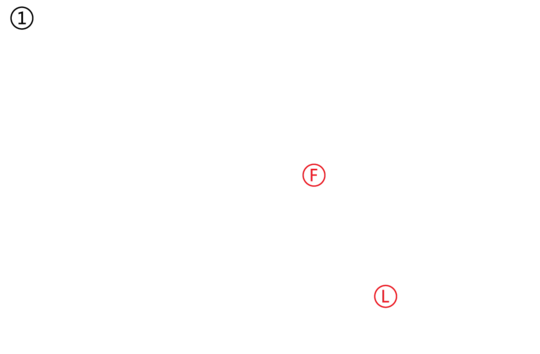
Begin the assembly by taking the chair backrest (F) out of the box and remove the protective plastic. Next, remove the pre-installed backrest 5mm bolts using the large hex key (L) on the right side of the backrest.
Repeat step 1 on the left side of the chair. Save the bolts.
Take the chair seat out of the box and remove the protective plastic. Next, remove the protective foam from the metal side brackets.
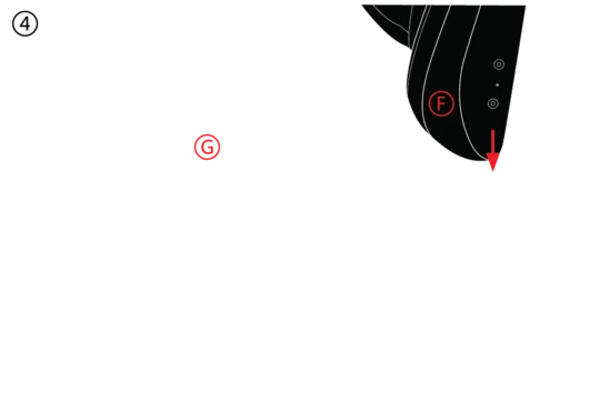
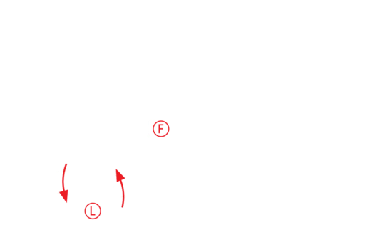
Align the backrest with the bracket on the left side of the chair.
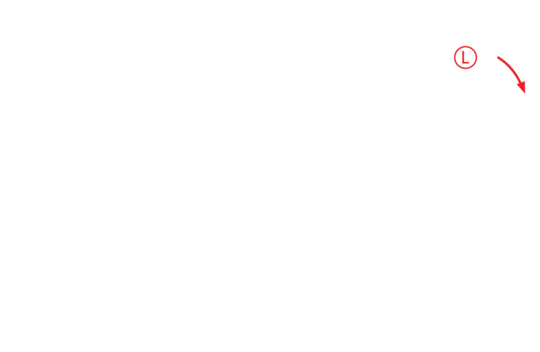
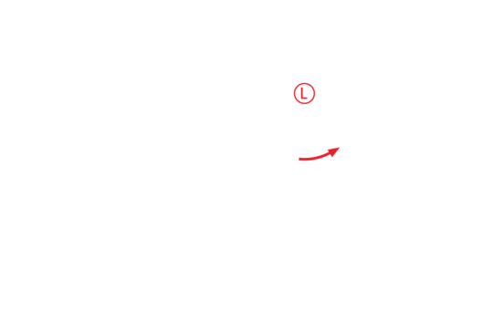
Attach the backrest using the 5mm screws you saved in step 1 and large hex key (L), by screwing them in loosely.
For safety reasons, avoid pulling the recline lever on the right side until the backrest is securely installed.
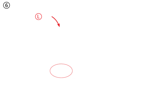
Align the backrest with the bracket on the right side of the chair. Attach the backrest
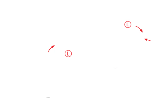
using the 5mm screws you saved in step 2 and large hex key, and tighten the screws on the left and the right side at this point.
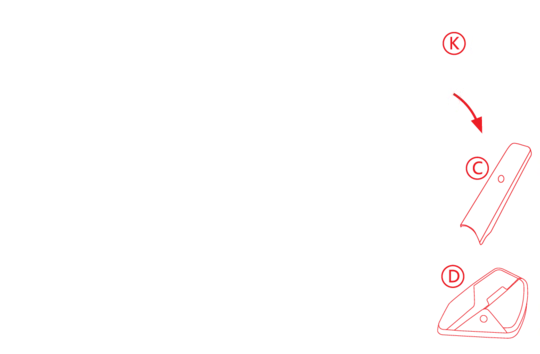
Using the small hex key (K) and side cover screws, mount the lower (D) and upper ( C ) side covers on the left side of the chair.
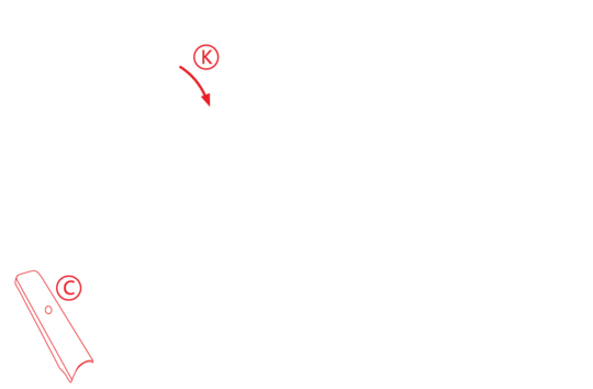
Using the small hex key (K) and side cover screws, mount the remaining upper ( C ) side cover on the right side of the chair.
Time to mount the mechanism (E) to the seat. Start by removing the preinstalled screws from the bottom of the seat using the large hex key (L) and save them.
Depending on the chair model you own, you’ll find the advanced mechanism (left) or standard mechanism (right) in the box.
Make sure the mechanism is being installed facing the front of the seat: the height adjustment lever should be on the left side and the large round knob to adjust the rocking tension is always towards the front of the chair.
Align the mechanism with the holes in the seat and use the screws you saved in step 9 to securely mount it.

Remove the red cap from the hydraulic gas lift (J) (if any) and put the gas lift cover (H) over the gas lift. Insert the gas lift into the mechanism.
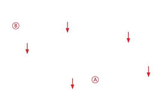
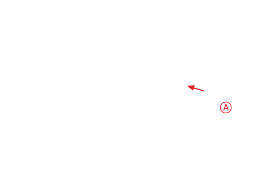
Place the wheelbase (A) upside down and insert the casters (B).
Lift the wheelbase and insert the hydraulic gas lift into the hole in the wheelbase. Carefully tilt the chair upwards while holding the wheelbase and position it upright. Assembly complete!
DESK ASSEMBLY GUIDE


FOOTSTOOL ASSEMBLY
